Yes waveforms looks a little better but with the oscilloscope put on DC coupling and not AC.
Regarding the amplitude I’d say around 17V : I put Volt/Div on 5 and I see 3 divisions+2 subdivisions (my oscilloscope has 5 subdivisions for each division… I prefer to precise as I am very new on this!)
Yes waveforms seem me clean in the experiments 1 and 2.
Please note I am using EDU09 software version 1.06 on windows XP running under virtual box hosted by Linux Ubuntu. I have tried also on another PC running under Windows 10 with similar results.
Using EDU09 for experiment 1, I find following value:
[list=]DC Mean=varying between -4.4 and 4.4
Max=18.1V
Min=-21.7
AC Rms=19.7[/list]
Wave is out of border (means that I don’t see top and bottom of the wave on my screen). Strange thing is when I change the volt/div this changes values displayed (example 19.6V with 5V/div is changed as 3.79v when changed to 1V/Div)
For experiment 4:
I have the same issue than described before. No way to see top/bottom of the wave, changing volt/Div doesn’t change the display but changes the values!
In fact as the EDU09 is a kit I mounted myself with a big help from you/your colleagues, I had preferred to test first EDU06 with my other oscilloscope which, as we saw before, doesn’t give the same wave than those expected…
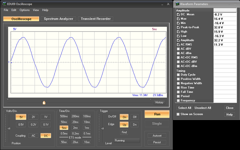
[quote]Strange thing is when I change the volt/div this changes values displayed (example 19.6V with 5V/div is changed as 3.79v when changed to 1V/Div)[/quote][quote]I have the same issue than described before. No way to see top/bottom of the wave, changing volt/Div doesn’t change the display but changes the values![/quote]This is normal operation if the waveform is “overdriven” so that positive and/or negative peak is clipped on the display.
If clipping occurs, the waveform parameters displayed are the max and min values on the current Volt/Div range (not real values of the input signal).
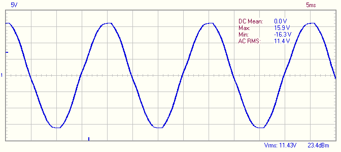
Here are two example screenshots.
In the first one the measured values are correct and in the second one ,due to clipping, they are false.
The question marks on the Waveform Parameters display indicate that clipping has occurred.
If the signal is clipping on the 5V/Div range, you can fix the problem by using a series resistor with the EDU09 input.
Using 100k resistor the input signal is attenuated to half.
Ok, for me form are different when using coupling AC but maybe there are some things I don’t understand yet. It part of the learning curve. I am now going to have a closer look and try to understand.
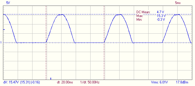
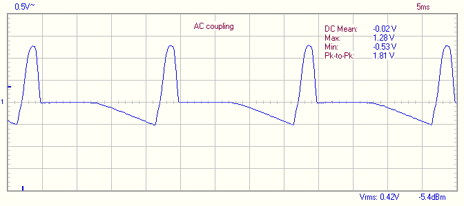
The waveform on point 5 using AC coupling is indeed very different:
When the AC coupling is selected, there is no DC current path to ground from point 5.
This point 5 between the diodes D6 and D5 is “floating” and the charging pulse of the electrolytic capacitor C1 is seen during the positive half cycle of the input signal.
During the negative half cycle the discharge of C1 is seen on point 5.
Anyhow everything OK
If you like, you can “fix” this AC coupling “issue” by adding a resistor between points 4 and 5 (e.g 100k).
Yes I’d like to fix this but I’d like also to avoid to destroy all !
My current understanding, when I look at the schematic view, is :
SK7 (corresponding to point 4, right?)
C1 (the capacitor)
D5 (corresponding to the diode)
SK3 (corresponding to point 5 isn’t it?)
What I don’t see, from a practical point of view, is where and how to add the 100K resistor. Must I cut a link somewhere between 2 of these components and install the 100k resistor?
Sorry is the question seems strange but I am discovering this world!
[quote]Must I cut a link somewhere between 2 of these components and install the 100k resistor?[/quote]No, there is no need to do any modifications or any soldering on the board.
The resistor can be added between the test clips of EDU09.
Connect the clips to points 4 (black) and 5 (red).
Add the resistor between the test clips.
Adding the resistor is just for test purposes to see the effect.
This way you can easily remove the resistor when the Experiment 4 is done.

 !
!