Dear All,
I’m learning edu-10 together with MPLABX with xc8 compiler using your included C example programs and it is very useful to understand the logics behind PIC microcontroller.
Now, I want to use MicroC program and would like to know:
- How to configure MicroC such that the pickit2 in edu10 is recognized so that it can be directly accessed from Micro C?
- How to import for example your analog_to_digital C example to MicroC?
- Which library (headers) and the definition in main.c should it be used?
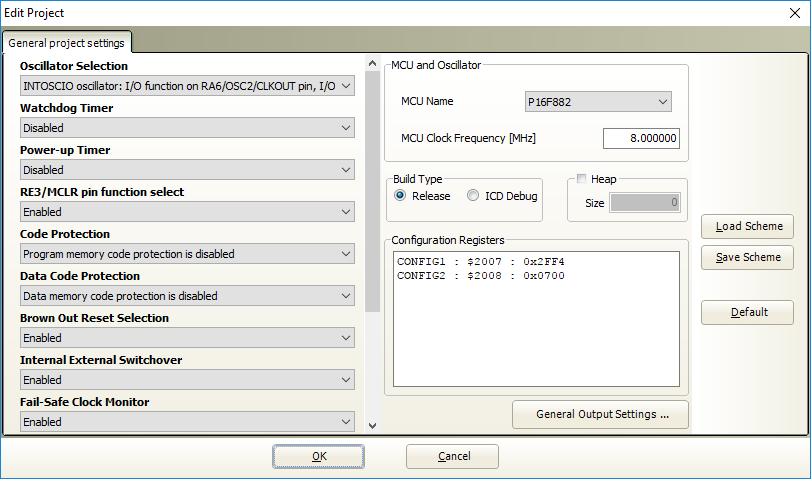
I’ve included part of the example code in MPLAB, which runs succesful within MPLAB X.
If we want to write similiar program in MicroC, how would it be look?
Thanks in advance
/*
- File: main.c
- Author: VEL255
- Created on 15/11/2012
- C Compiler Demo for the EDU10 Board.
- Analog-to-Digital converter
- This code uses the PIC16F882 ADC to read the value of the VDR, NTC and RV1.
- The eight most significant bits of the ADC result is converted
- to value 000-255 and displayed on the 7-segment display.
- Buttons are used to select the analog input device:
- SW1: LDR
- SW2: NTC
- SW3: Potentiometer
- SW4: Potentiometer is used to adjust the buzzer tone pitch.
**********************************************************************/
//#include <stdio.h>
//#include <stdlib.h>
//#include <stdint.h>
#include <xc.h>
//------------------------------------------------------------------------------
//PRAGMA’s
#pragma config CPD = OFF
#pragma config BOREN = OFF
#pragma config IESO = OFF
#pragma config DEBUG = OFF
#pragma config FOSC = INTRC_NOCLKOUT
#pragma config FCMEN = OFF
#pragma config MCLRE = ON
#pragma config WDTE = OFF
#pragma config CP = OFF
#pragma config LVP = OFF
#pragma config PWRTE = OFF
#pragma config BOR4V = BOR21V
#pragma config WRT = OFF
//------------------------------------------------------------------------------
//DEFINES
#define LD7 PORTCbits.RC7
#define LD6 PORTCbits.RC6
#define LD5 PORTCbits.RC5
#define LD4 PORTCbits.RC4
#define buzzer PORTCbits.RC0
#define offLD PORTC &= 0b00001111
#define SW1 PORTAbits.RA4
#define SW2 PORTAbits.RA5
#define SW3 PORTAbits.RA6
#define SW4 PORTAbits.RA7
//------------------------------------------------------------------------------
//DECLARATIONS
void init (void);
unsigned char buttons (void);
void show(unsigned char value);
void beep (unsigned char pitch);
unsigned char ntc (void);
unsigned char ldr (void);
unsigned char pot (void);
void delay (void);
unsigned char delayDisplay (void);
unsigned char button;
const unsigned char segments7 = {
0b00111111, // 0
0b00000110, // 1
0b01011011, // 2
0b01001111, // 3
0b01100110, // 4
0b01101101, // 5
0b01111101, // 6
0b00000111, // 7
0b01111111, // 8
0b01101111 // 9
};
//------------------------------------------------------------------------------
//CODE
//------------------------------------------------------------------------------
void main (void)
{
init();
while(1)
{
buttons();
switch (button)
{
case 1: show(ldr()); break;
case 2: show(ntc()); break;
case 3: show(pot()); break;
case 4: PORTB = 0;
beep(pot()); break;
}
}
}
//------------------------------------------------------------------------------
unsigned char buttons (void)
{
if (SW1 == 1)
{
offLD;
LD7 = 1;
button = 1;
return 1;
}
if (SW2 == 1)
{
offLD;
LD6 = 1;
button = 2;
return 1;
}
if (SW3 == 1)
{
offLD;
LD5 = 1;
button = 3;
return 1;
}
if (SW4 == 1)
{
offLD;
LD4 = 1;
button = 4;
return 1;
}
return 0;
}
<<<<<<
