EDU09 Passes Calibration but does not operate correctly

Hi,

I’ve just completed the EDU09 kit (my first level 4 difficulty Velleman Kit).

Initially the kit failed calibrartion but this forum pointed me in the right direction (I had IC2 the wrong way round).

Now, when I connect the kit to any signal it does not respond.

The software display shows a signal but this does not correspond to the connected signal.

Could anyone offer me any advice on how to proceed and what I can do to test where I’ve gone wrong?

I can provide pictures / voltages if someone would let me know what would be useful.

Many thanks for your help.

Yes please post pictures of the signal and pcb

Best Regards
VEL337

I wasn’t sure how to upload images to this board so instead placed all files in a Google Share at https://drive.google.com/folderview?id=0B1AMurf2j-JAdlY1MkZkOC1lZFE&usp=sharing.

The folder contains:

  • image of front of board

  • image of back of board

  • calibration.log file

  • saved images of software when running in three states (apologies, I got my numbering mixed up on the images):

        - 2 - display and DSO file for screen when first turned on
        - 1 - display and DSO file for screen when either +ve and/or -ve probes are toucing something (e.g. my finger)
        - 3 - display and DSO file for screen when connected to 9v DC source
    

If I’ve missed anything here or if there’s anything else I can show that will help then do let me know.

Many thanks.

The calibration values are OK.
Also the screenshots seem to be OK.

[quote]- 3 - display and DSO file for screen when connected to 9v DC source[/quote]Please select 5V/Div or 2V/Div range. Select DC coupling to measure DC source.
Please do not use Autoset for DC measurement.
Autoset turns always AC coupling on.

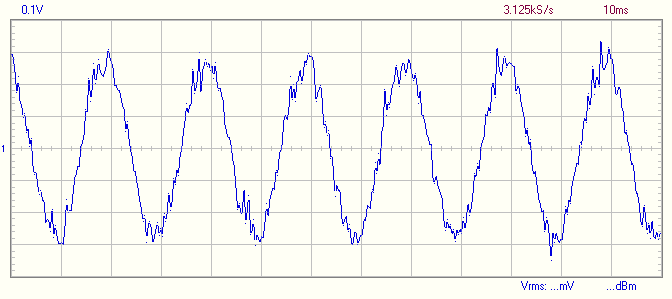
[quote]- 1 - display and DSO file for screen when either +ve and/or -ve probes are toucing something (e.g. my finger)[/quote]Please select Time/Div range 10ms to see some 50Hz waveform on the screen.
You should see something like this when touching the red probe with your finger:

When touching red probe with finger and selecting options as requested (range:2V/Div, DC coupling to measure DC source, Autoset off, time/div range 10ms) results in screen shot 4 (uploaded to the same Google Share as above).

I noticed on your screen shot that you had 0.1V/Div selected - trying this results in screen shot 5.

You’ll notice that this doesn’t match yours.

Indeed, doesn’t match. You may have very “low noise” environment.
Do you have any known signal source to test e.g. a little transformer with low voltage AC output.
Also you can check the operation with known DC sources e.g. batteries.

Hi,

checking with several different batteries does not show any difference to the display. (Shows same as when nothing is connected or finger touching probe).

I have a Velleman MK105 Signal Generator (an earlier project) which also, when connected makes no difference to the signal displayed.

If you have a multimeter, please check the probe leads are not broken.
Especially check the black lead is connected to the ground plane.

If leads are OK, then check the relay is OK.
When DC coupling is selected the C1 should be short circuited via the relay.

That’s it!

The ground lead was broken in the middle of the cable.

Just tested again with the Velleman MK105 Signal Generator and I get a perfect sine wave.

Many thanks for your assistance.

Could you tell me if there’s any particular specification I should be looking for when looking for replacement leads?

Looking at this post: http://forum.velleman.eu/viewtopic.php?f=46&t=11671 I note that it may be possible to replace the existing SK1/SK2 connections with a BNC connector so I may go this route.

1 Like

I’m glad to see it’s working now!

[quote]Could you tell me if there’s any particular specification I should be looking for when looking for replacement leads?[/quote]There are no special requirements. I think any flexible cable will do the job.

Thanks you so much for your patience and helping me get this problem sorted so quickly!

Well done Velleman!

I’ve got a similar Problem, but I haven’t put the IC’s in with the notch to the false direction…
It passed Calibration, afterwards I connected it with the EDU06 and got a noisy line on 0,1 V (autoset…)
On the Pictures you can see one Picture with a small sinuswave - on this Picture i connected only the red cable which was connected to the IN-Port on the board…

These Pictures are on my GoogleDrive-folder: drive.google.com/drive/folders/ … sp=sharing

Your EDU09 seems to be working.
There may be some problem in the input section.
What is the result if you connect the test leads to a battery (e.g. 1.5V) ?
Use DC coupling in this case.

I connected it to an 1,5V AA-battery - as you said to me - but I got almost the same Pictures. It showed me again a voltage about 0,0V-0,1V although the battery was new

Please do following tests to locate the problem:

  • Run the EDU09 program and select the DC coupling and 0.1V Volts/Div range.
  • Connect 1.5V battery between the test leads
  • Use multimeter and check the voltage on following points:
  • Use one of the four mounting holes as ground reference (at the corners of the board).
  • Check voltage on SK1 (where the red test lead is connected). There should be 1.5V
  • Check the voltage on both ends of C24 (C24 is located next to relay RL1.) There should be 1.5V.
  • Check the voltage on pin 1 of IC1 (this is the pin next to label “IC1” on the board). There should be 0.37V.
  • Check the voltage on pin 3 of IC1. There should be 0.37V.

I had the same problem, except in my case the red cable was broken somewhere. I’ll find a new cable and resolder.