I am using the EDU09 as my project for my class. I am doing a circuit analysis, and I am having trouble figuring out IC2B. I know it is an integrator, and i’m not sure exactly why. It goes up to IC2A and to pin 12 on the pic.
IC2B is used to output stable -1.65 voltage to feed through R23 to the inverting input of IC2A.
This forces the output of the IC2A to rise proper positive level (about 1.65V) for the ADC input of IC3.
Pin 12 of IC3 outputs PWM signal, filtered to DC with R10, C14, R9, C15.
This DC is used to adjust the average output voltage level of IC2A to adjust the Y-position of the trace on the oscilloscope screen.
The integrator circuit around IC2B provides just a lowpass function to eliminate possible noise of its input signal +3V3.
Thank you, I know IC1 is selecting which channels go through, but i’m not sure why the signal is ran through the voltage divider. I was also wondering how some of the pins on IC3 are programmed. I know many of them, but i’m not sure about pin 7. Is is it to tell IC3 how to adjust the PWM? I’m also not sure about why r 19 goes to ground. Are diodes d5 and d6 acting as protection for IC3 input pins 2 and 5? I’m sorry for so many questions. Thanks again for answering my previous questions.
The voltage divider is used to expand the input voltage range.
If not used, the input voltage range would be limited about range from VEE (-5V) to VDD (+5V).
If the input voltage is more positive than the supply voltage, VDD (typically 0.7 V higher than VDD), or more negative than the supply voltage, VEE (typically 0.7 V lower than VEE), then the internal ESD diodes of IC1 get forward-biased.
The internal diodes together with R28 protect IC1 from overvoltage transients and from abnormal high input voltage too.
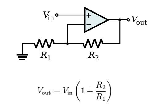
This pin is used to change the gain of IC2A.
The gain is doubled on 1V/Div and on 0.1V/Div ranges.
This is done by setting the pin 7 as an output and pulling it to GND.
On other V/Div ranges pin 7 is set as an input, being in a high impedance mode (also known as hi-Z, tri-state, or floating).
It is used to set proper gain for the amplifier IC2A.
Here is the equation for the gain of non-inverting amplifier:
Yes, they are. Together with R13 they limit the input voltage to safe range.
Thank you for all of your help, this has allowed me to complete my circuit theory paper for class.
No problem, glad to be of help.