I measured the voltage on pin 7 of ic1 and read 0.71 volts.
I measured the voltage between the anode of the zener diode and ground (that I took on SK3): -4.80 volts.
The measurement of the pin 7 of the ic1 I have performed with respect to ground.
I live in Trieste, Italy, and it would be problematic to ship in Belgium. What is the problem?
Please do following:
Disconnect the USB cable.
Use ohmmeter to check the connection between the anode of the ZD1 and pin 7 of IC1.
It seems that there is a trace break on your EDU09 board between these points.
Try to locate the break by following the trace step by step.
First step is to check the connection between ZD1 anode and electrolytic capacitor C31.
If OK, then check connection between C31 and IC1.
I measured and the continuity between the zener diode and capacitor C31 was a loose contact. I unsoldered the zener diode and settled on a lead pitch of the cathode of ZD1 and another on the pitch free near C19 which I found to be connected to the negative of the C31. I put the zener diode in a breadbord and I connected to the anode of the thread pitch (the one nearest to C19 and connected to the negative of C13), while the cathode with the other wire to ground.
Result: I measure the pin 7 of IC1 the usual 0.71 volts in my little experience diode is conductive and non-operating zener!
[quote=“GabrieleV”] I measured the voltage between the anode of the zener diode and ground (that I took on SK3): -4.80 volts[/quote]If you now solder the ZD1 back to its original place on the boar, do you get -4.8V between its anode and ground?
This indicates that the zener diode is OK.
[quote=“GabrieleV”]I measured the voltage on pin 7 of ic1 and read 0.71 volts.[/quote]There should be same voltage on ZD1 anode and on pin 7 of IC1 compared to ground.
These two points should be connected together.
hi, I tried to see the continuity between the points indicated in the picture but there is no connection. With a lens I saw the track and detached from the pitch! attaching photos of mosssa I had previously done.
I await response
[quote]hi, I tried to see the continuity between the points indicated in the picture but there is no connection.[/quote] You can fix this problem by adding a piece of wire between the points indicated in your picture.
After doing this there should be -4.8V on pin 7 of IC1.
Hello, I have the same problem. Calibration error 59,-201, 201,200,200, however I have checked the connection between the anode of the ZD1 and pin 7 of IC1 and between C31 and IC1 and there is no problem of connectivity.
On the other hand the voltage between anode of ZD1 and ground is -0.7V. What can I do to spot the problem?
[quote]On the other hand the voltage between anode of ZD1 and ground is -0.7V.[/quote]This may indicate the IC2 is in reverse polarity.
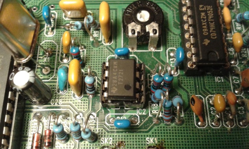
Here is a picture showing how IC2 should be assembled:
Hello. The notch of IC2 is in the right position. Which values of voltage should be achieved? A map with the voltage values in each spot could be usefull.
After step 2 should i have to insert again IC1 and IC2?
Anyway the voltages measured without IC1 and IC2 and ZD1 out of operation (During the operation of taking out the cathode of ZD1 I damage this component) are:
It seems the diode D4 is defective or not connected.
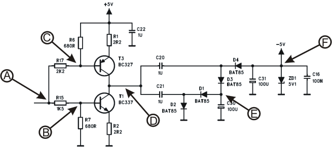
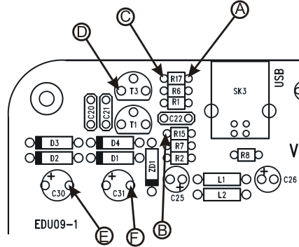
Please check the points marked with blue are connected together and the points marked with red are also connected together:
If possible, test also the diode D4 with the diode tester of the multimeter.
[quote](During the operation of taking out the cathode of ZD1 I damage this component)[/quote]I’m sorry for the inconvenience.
If the problem is found (maybe around D4) there should be about -8V at F, and also on the anode point of ZD1.
In this case, do not place the IC1 and IC2 back to the sockets before the zener diode ZD1 is replaced.
There should be -5V at point F when everything OK.
Hello.
“It seems the diode D4 is defective or not connected.
Please check the points marked with blue are connected together and the points marked with red are also connected together:”
I have checked the diode D4 and apparently is OK. Checked the points marked with red and also the ones with blue and connectivity OK. However have find out if in the moment I turn on the board (by plugging USB) the voltage in F is very low (if I had discharged C31 before plugging) and stay (measuring F the voltage remains low). If I try to measure the voltage in D4, I find out that the voltage at F jumps to -9V (due to the multimeter???). I have tested with a new multimeter and the same happens, but if only I try to measure D4. If, for instance, I just measure F, nothing happens.
Another information … connectivity between F and blue spots OK. Could be a problem of diode or capacitor?
I have another question. From where I should obtain -8V. Which part of the circuit feeds F spot (where is the source)?