Hi.
(I’m sorry, my english is not very good. I’ll try my best)
I’ve assembled the edu09 oscilloscope kit but I’m having some problems.
During the assembly I broke the PCB trace from ‘‘HI_GAIN’’ to R18 pin (looking at the electrical diagram). I soldered a wire from the R18 pin to the IC3 pin 7 hoping it would repair the connection.
When I connect the scope to the computer, the scope is recognized and the EDU09 program says that the calibration is successful. I have these results:
Calibration results:
CH1 offset at 2V/div : 131 OK
Rounds : 4
CH1 offset at 1V/div : -1 OK
Rounds : 7
CH1 Y-position low, CH1_DAC1 32 32
Rounds : 1
CH1 Y-position mid, CH1_DAC0 128 133
Rounds : 6
CH1 Y-position high, CH1_DAC2 224 225
Rounds : 2
I’ve looked up at some threads in the forum and I’ve done these measurements with a multimeter:
Volatge readings:
IC1
1 0
2 0
3 0
4 0
5 0
6 0
7 -5.13
8 0
9 4.96
10 0
11 0
12 0
13 0
14 0
15 0
16 0
IC2
1 4.89
2 0.37
3 0
4 -5.13
5 0
6 0
7 -1.65
8 4.96
Voltage readings according to the picture:
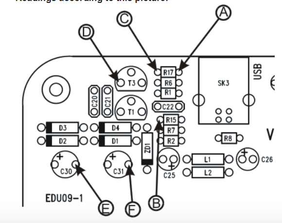
A 1.66
B 0.43
C 4.35
D 2.56
E -2.52
F -5.13
Now when I try to use the scope I have these results:
- With the 5v, 2v and 1v divisions, if the probes are not connected, the trace on the scope window is at zero. If I connect a 9v battery the trace measures 3v, if I connect a 1.5v battery I get no readings.
- With the 0.5v division, with the probes not connected, the trace ‘‘jumps out of’’ the window.
- With the 0.2v, 0.1v divisions, if the probes are not connected the trace is not at zero, it measures some kind of singal with variable ripple and DC component, around 0.8v ±0.1v.
Can someone give me an advice ?