I have a block of relays, which snaped into action when there are TTL signals on input of the relay. And i want to control this relay through my VM110 card…But the voltage from digitals output of VM110 is too small…I suppose the digital outputs isn’t support ttl signals…Am i right?
And what can i do to send the TTL signal by using the digitals outputs of VM110?
The outputs of the VM110 are NPN open collector transistor outputs.
Please see the page 19 of the manual how the relays should be connected between the CLAMP and the output. Connect external +5V between the CLAMP and GND.
[quote=“VEL255”]The outputs of the VM110 are NPN open collector transistor outputs.
Please see the page 19 of the manual how the relays should be connected between the CLAMP and the output. Connect external +5V between the CLAMP and GND.[/quote]
Thanks for help! You mean i must see page 8 of the manual because there are only 11 pages in manual for vm110…
I see the scheme…And if i connect the external 5V to CLAMP and GND, i will be able to get +5V between GND and DigitalOutputChannel when the channel are set and 0 when the channel cleared, am i right?
Sory for stupid questions, because i’m not good at circuit technique.
I connect the voltage and relay exactly as describe in scheme/ But i have a another problem…I connect exactly +5V to the CLAMP and GND but when i set the digital channel i have only +4.5V between CLAMP and output when the channel set, and that’s why my relays not switching…
Any idea to solve this problem? Unfortunately i can’t connect more high voltage because i take it from the computer where +12V used for relays and +5V i connect to VM110
Is your relay coil connected between the CLAMP and the digital output?
You may connect more than one digital outputs in parallel to the relay. This may slightly increase the voltage. If no help, then the only solution seems to be to connect higher voltage to the CLAMP terminal.
Sorry but this is not quite clear to me. What do you mean by:
if i connected the external 5V, as shown in the manual, i always have +5v at the clamp and my relay always switch on…May be i make wrong connection…
here is my connection
- from external DC to clamp
- to GND
Clamp to GND (don’t work because at clamp always +5v)
Output to Input relay
And one more qustion… i have 4 channel relay where one ground for all 4 channel and 4 input…How can i connect 4 output to 4 input when the CLAMP is + , not the GND 
What is a 4 channel relay? Do you have any datasheet or circuit diagram of it? What is written on its cover: Manufacturer, type … ?
Here is the link masterkit.ru/main/set.php?num=551
Sory but it’s not at english but there is the scheme in there…
Thank you, this link helps a lot to understand your problem.
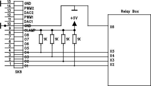
Connect +5V between the CLAMP and GND of the VM110.
Connect 1k ohm pull-up resistors between the CLAMP and the outputs O1, O2, O3 and O4.
Connect the GND of the VM110 to terminal X6 of your relay unit.
Connect the outputs O1, O2 O3 and O4 to the inputs X2, X3, X4 and X5 of your relay unit.
thanks for help, but the scheme which you are posted didn’t work too, because at the digital outputs there are always voltage and when i connected outputs to relay board, relays starting switching even without the ground wire!
But i find out how to solve my problem…I connect +12v to CLAMP and GND and connect digital outputs directly to relays (not to the inputs of relay boards). Thus if the digital is high, relay switches and if it’s low, relay goes back to initial state…
Unfortunately, before i solve my problem, i make the wrong connection and fuse VM110 
Now, i have only 3 digitals outputs, which are working and i can not connect external voltage to the board, because GND and CLAMP a fuse now too
Good to see that you found a solution:
Sorry about your unlucky connection that caused the ULN2803 to break.
You are lucky: The microcontroller IC3 is still OK. You have only to replace the IC4.
I thinking about repairing card…How do you think i may just replace IC4 without any other actions? Or i need to do something more(may be upload programm to microcontroller) with IC4?
in case if the only IC4 is broken…
You may check that only the IC4 is defective:
- Remove IC4.
- Change IC2 to the socket of the IC4.
- Test with the software and with your relays that everything works OK.
You may use the digital output LEDs (LD1…LD8) to check that the microcontroller is OK. Use the demo software to turn individual LEDs on and off.
The output LEDs of 7 channels idicates all correctly, but realy works only 3 channels. And between GND and CLAMP there are no resistanse(thus i can not use external voltage)…any idea of this problems?
Did you replace the IC4 (with IC2) as I wrote in the previous post?
Not yet…I have not got VM110 now, i can replace IC4 and tested card only tomorrow…
I replaced IC4 with IC2 and seems that digital outputs are working fine. thanks for your advice… And now i’m going to find the place where i can buy IC4…