Since 1987 I’m doing pretty much everything in C. Except for graphics, those I’m doing in Tcl/Tk. Not the most popular language, but I don’t care.
The PIC18F2550 I’m using on my K8055 is programmed in C. The PIC18F24J55 used on the K8055N is almost identical. So now I’m on my home turf … watch out!
I did some math on the DCC protocol specifications. A “1” bit is 116µs long (2×58µs) and a “0” is ≥ 200µs. A Baseline Packet consists of a Preamble of 12 “1” bits, 3 bytes, each preceded by a “0” bit, and a final “1” stop bit. The first byte is the address, the second the actual command and the third a trivial XOR check sum of the previous two. Assuming an equal distribution of 1s and 0s, this makes a Baseline Packet 5900µs long on average. The Extended Packet Format allows up to 6 bytes length, but they still follow that same pattern; Preamble of 12 “1” bits, 3-6 bytes consisting of “0” plus 8 data bits each, “1” stop bit.
The firmware of my modified K8055 currently uses an internal 100µs Ticker, triggered by a timer interrupt. Using that timer interrupt instead to toggle the state of an output port, so that it outputs DCC packets, would be absolutely no problem at all. However, since the timer is also used to do the precise on/off timing for the Servo Pulses, these two features may be mutually exclusive on a single board. But that is no big deal since the “DCC->Servo” decoder, I envisioned earlier, apparently exists already. tamvalleydepot.com/products/ … coder.html
So here is how the entire thing would work:
[ol][li]One gets either a K8055N/VM110N or does the hardware modification of a K8055/VM110 to the PIC18F2550 chip. I have a K8055N on my Xmas shopping list. Might have to order that one early, plus a spare PIC18F24J55.[/li]
[li]Create a new firmware branch that starts with the original K8055 compatible code.[/li]
[li]Extend the protocol and firmware. A status bit in the cards report will show that the K8055 is ready to receive a new DCC packet. A new command message type sends a DCC packet of 3-6 bytes length to the card. The card starts sending that packet on output port O8. During that the status bit is off and another DCC send command will be ignored. When done, the status bit comes back on. [/li]
[li]Flash the new firmware into a PIC and put it onto the K8055(N).[/li][/ol]
The K8055(N) would be completely ignorant of the actual content of the packets. Those byte values are entirely up to the controlling PC software. This K8055(N) would be capable of controlling anything that conforms to the DCC packet format of 12x"1", “0” 8-bits, … , “1”. I didn’t read up on that MERG CBUS stuff. Is that using a different packet format? If so, well, maybe not supported in version 1.0.
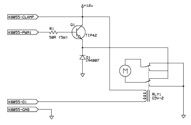
What is missing is some circuitry that, controlled by the K8055(N) output port O8, will reverse a DC voltage. Probably power transistor based. That shouldn’t be terribly difficult and only cost about $10-$20 in parts. A suitable PIC to replace the one coming with a K8055(N)/VM110(N) costs less than $5.
Here is the problem: End users don’t regularly flash PICs. They don’t have PIC programmers. This is why almost nobody has ever done the K8055 hardware modifications, I described here: viewtopic.php?f=3&t=7480#p28184
End users also don’t regularly build custom circuits on breadboards. And with the voltage and currents we are talking about here, this may actually be a good thing. Wiring that stuff the wrong way can cause some serious damage.
If this should be used by other RR model enthusiasts, you would have to offer the voltage reversal circuit together with a pre-programmed PIC and your control software as a bundle. The user then only has to get a regular K8055N/VM110N board, exchange the PIC (which is in a socket, so that’s easy enough), connect the wires and be ready to go. From there, new firmware updates can be flashed via USB bootloader. The user doesn’t even have to touch the hardware any more.
This custom K8055 could still do up to two of the PWM controlled trains, we discussed initially. And have 5 digital inputs, 2 analog inputs and 5 digital outputs spare so far. I can see an analog input sensing a photo resistor, so that your model world reacts to dimming down the lights. I know, I’m evil.
Regards,
Jan
