[quote] I would have sent you a full table of measurements carried out by me on this site unfortunately I can not post attachments[/quote]You can upload the data to a free file hosting service and post the link here.
Please look at my measurement table, if you have any questions please ask.
Table Measure Pin7 of IC12 cloud.mail.ru/public/DFkA/x8Fp94tw5
If you can send the data voltages of the key points for the test mode, so I can compare the readings. Thank you.
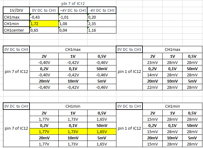
Here are the measurement results of calibrated PCSU1000:

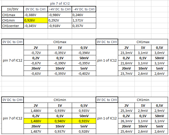
Here are your test results of the defective PCSU1000:
The output voltage on pin 7 of IC12 seems to be too low on most of the V/Div ranges.
The very bad calibration values may cause this problem too.
As a test to check how big damage there is, you can do following:
Replace the content of the WinDso.ini with the following data.
This data is copied from my PCSU1000’s WinDso.ini file.
Then try to use the oscilloscope but do not calibrate it.
[Hardware]
DemoMode=0
ExtendCalTime=0
LPT_Port=4
LPT4=888
HW_DSO=1000
USB_Recorder=0
[Path]
FilePath=C:\Program Files (x86)\Velleman\PCLab2000SE
[Menu_500]
No_Gen=0
Hide_Scope=0
No_Scope=0
BrightGrid_rec=0
BrightGrid_dso=0
Dot_Join=1
HWdialog=1
RMS_on=0
dBm_on=0
Rate_on=0
NoNote=1
LPT_Speed_Slow=0
SaveRecallLastSettings=0
ShowHistoryHint=1
[Menu_1000]
No_Gen=0
Hide_Scope=0
No_Scope=0
BrightGrid_rec=0
BrightGrid_dso=0
Dot_Join=1
HWdialog=0
FolderCreated=1
RMS_on=0
dBm_on=0
Rate_on=0
NoNote=1
LPT_Speed_Slow=0
SaveRecallLastSettings=0
ShowHistoryHint=1
ClearDisplay=0
Ch1RiseFallThreshold=0
Ch2RiseFallThreshold=0
Ch1WidthThreshold=1
Ch2WidthThreshold=1
[Menu_8031]
No_Gen=0
Hide_Scope=0
[Menu_100]
No_Gen=0
Hide_Scope=0
[Status]
Running=0
[ScopeMainForm_1000]
Top=30
Left=214
Width=809
Height=589
Probe_CH1=1
Probe_CH2=1
Status=1
[EditForm_1000]
Width=300
Height=267
[EditForm_500rec]
Width=300
Height=264
[Big_Screen]
Top=113
Left=20
Width=1009
Height=630
Visible=0
[Big_Screen_ctrl]
Top=3
Left=98
Width=755
Height=298
[ThresholdOptions]
Top=32
Left=43
[Wave_Parameters]
Top=104
Left=111
Width=375
Height=485
[Calibration_1000]
trg_ch1_min=48
trg_ch1_mid=91
trg_ch1_max=134
trg_ch2_min=47
trg_ch2_mid=90
trg_ch2_max=134
trg_ext_mid=49
offs_1=122
offs_2=119
v5_offs1=1
v5_offs2=2
v15mv_offs1=5
v15mv_offs2=5
v5mv_offs1=0
v5mv_offs2=0
f5us_offs1=1
f10us_offs1=0
f20us_offs1=0
f5us_offs2=1
f10us_offs2=0
f20us_offs2=0
Ch1_pos0=127
Ch1_pos1=31
Ch1_pos2=223
Ch2_pos0=128
Ch2_pos1=31
Ch2_pos2=223
Ch1_ad0=121
Ch1_ad1=75
Ch1_ad2=165
Ch2_ad0=119
Ch2_ad1=73
Ch2_ad2=163
[Persistence]
NormalPersistence=1
Persistence_with_Intensity_Grading=0
VariablePersistence=0
Number_of_Acquisitions=0
LowColor=1
HighColor=10
Duration=15
Duration2=127
[Colors_1000]
DefaultColors=1
Background=16121855
Ch1=16711680
Ch2=255
Math1=16711808
Math2=16711935
Dark_Grid=12632256
Bright_Grid=8421504
Time_Marker=4194432
[ScopeMainForm_500]
Top=4
Left=3
Width=743
Height=580
Status=1
[EditForm_500]
Width=299
Height=266
[Calibration_500]
trg_ch1_min=100
trg_ch1_mid=128
trg_ch1_max=156
trg_ch2_min=100
trg_ch2_mid=128
trg_ch2_max=156
trg_ext_mid=85
offs_1=128
offs_2=128
v5_offs1=0
v5_offs2=0
v15mv_offs1=0
v15mv_offs2=0
v5mv_offs1=0
v5mv_offs2=0
f5us_offs1=0
f10us_offs1=0
f20us_offs1=0
f5us_offs2=0
f10us_offs2=0
f20us_offs2=0
Ch1_pos0=128
Ch1_pos1=32
Ch1_pos2=224
Ch2_pos0=128
Ch2_pos1=32
Ch2_pos2=224
Ch1_ad0=128
Ch1_ad1=62
Ch1_ad2=192
Ch2_ad0=128
Ch2_ad1=62
Ch2_ad2=192
[Colors_500]
DefaultColors=1
Background=0
Ch1=65535
Ch2=65280
Math1=16777215
Math2=16711935
Dark_Grid=8388608
Bright_Grid=16711680
Time_Marker=16776960
If you are using Windows Vista, 7, 8 or 10 32-bit, the file WinDso.ini is located in folder:
C:\Users<UserName>\AppData\Local\VirtualStore\Program Files\Velleman\PcLab2000SE
If you are using Windows Vista, 7, 8 or 10 64-bit, the file WinDso.ini is located in folder:
C:\Users<UserName>\AppData\Local\VirtualStore\Program Files (x86)\Velleman\PcLab2000SE
In older operating systems the file WinDso.ini is located in folder: C:\Program Files\Velleman\PcLab2000SE
Good day. I replaced WinDso.ini content and that’s what I got …
cloud.mail.ru/public/4otr/Whz83mYGk
As you can see the measurement we have almost coincided besides pin 1 of IC12. Tell me, what else should pay attention. Thank you.
I think the voltage values on pin 1 of IC12 are mV values?
If yes, they are good.
It seems the oscilloscope input section is OK.
What do you get on the screen when measuring “real” signal waveforms, e.g. sine wave?
There seems to be some problems with the calibration - so do not calibrate yet.
Yes you are correct measurements on pin 1 of IC12 are mV. Although we have almost all of the values except for this match, unfortunately oscilloscope behaves not quite correct. I’m sending you a photo of the test measurement input (square wave) with different ranges. And the signal line is also shifted down, although the settings slider is in the middle. The calibration of the oscilloscope does not pass calibration.log file in the same folder with the photos.
cloud.mail.ru/public/Cfxe/M6jC8ApeN
Thank you!
It seems that some bits are not transferred correctly from scope to PC.
Please check the IC25 pins are properly connected.
Especially check pins 18 up to 22.
Good afternoon. Sorry for the absence, I was on a business trip. I checked all the contacts on IC25 are well sealed. Do you think the chip itself may be faulty or is there more options? Thank you.
Connect to the scope input signal high enough to get calculated full screen trace movement on the screen.
Then check the voltage on pins 18, 19 and 20 of IC25.
You should get some indication of varying voltage on these pins.
If there is no voltage change on these pins, it may indicate the FPGA IC18 may be damaged.
