I had some initial problems with the assembly of EDU09. Several resistors were missing in the kit. Resistors R8-R13 were 100 ohm instead of 1kohm as stated in the aassembly manual and in the circuit diagram. I replaced these resistors from my own supply R8-R13 1k. However there was no R23 11k and I replaced it with 10k because 11k is a rather unusual value that I didn’t have.
I now have a problem with the calibration:
But have you try using the specified value for R23 ? You may need to try adding a 1k resistor in series to the 10k resistor? (1k + 10k = 11k ?) (or whatever resistors you have that give you cumulated in series, a resistor values of 11k )
It’s verry strange that there are resistors missing in this kit. We do for every prouduction batch of our projects kits a production check: (BOM list) before and after production
But there are 2 types of resistors in this kit. 4 and 5 bands resistors! So pay attention!
This tool can also help: (set tool onto 5 band).
4 bands; regular carbon resistors.
5 bands; Metalfilm precision resistors (blue colored resistors) The 5 bands in illustration manual are marked with * to pay attention on it.
R5-7: 680Ω (6 - 8 - 0 - 0 -1)* bleu 6 / gray 8 / black 0 / black x1 / brown (1%)
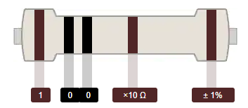
R8-13: 1KΩ (1 - 0 - 0 - 1 - 1)* brown 1 / black 0 / black 0 / brown x10 / brown (1%)
R14 : 1K1 (1 - 1 - 0 - 1 - 1)* brown 1 / brown 1 / black 0 / brown x10 / brown (1%)
R19 : 5K1 (5 - 1 - 0 - 1 - 1)* green 5 / brown 1 / black 0 / brown x10 / brown (1%)
R20 : 7K5 (7 - 5 - 0 - 1 - 1)* violet 7 / green 5 / black 0 / brown x10 / brown (1%)
R21-22: 10KΩ (1 - 0 - 0 - 2 - 1)* brown 1 / black 0 / black 0 / red x100 / brown (1%)
R23: 11KΩ (1 - 1 - 0 - 2 - 1)* brown 1 / brown 1 / black 0 / red x100 / brown (1%)
R24: 15KΩ (1 - 5 - 0 - 2 - 1)* brown 1 / green 5 / black 0 / red x100 / brown (1%)
R25-27: 20KΩ (2 - 0 - 0 - 2 - 1)* red 2 / black 0 / black 0 / red x100 / brown (1%)
R28: 75KΩ (7 - 5 - 0 - 2 - 1)* violet 7 / green 5 / black 0 / red x100 / brown (1%)
4 Band resistor:
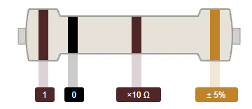
R3-4 : 100Ω (1 - 0 - 1 - B) brown 1 / black 0 / brown x10 / B Gold (5%)
Is it possible to upload hi resolution photo (clear photo) of Solder side PCB (Bottom) and Component side of PCB (TOP).
I measured all the resistances of the resistors in the kit with a multimeter. The number of resistors did not total the correct number in the manual there were fewer resistors.
There were no 1k resistors in the kit and instead six 100 ohm resistors Se attached photo where you can se the pattern on the: brown-black-black-back—brown.
There was no 11 k resistor.
I replaced the 100 ohm resistors with six 10k resistors that I had so that was really no problem. I put a 10k resistor in place of the 11 k resistor as I didn’t have any 11k. If necessary I can series couple that resistor with a 1k resistor that I have It would be difficult to replace a once soldered in resistor .
I attach zippes links to photos of the PC board both sides and a picture of the R8-R13 resistors.
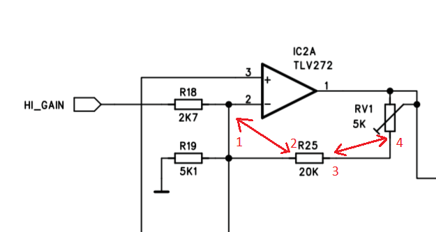
There seems to be problem only with the voltages on pins 1 and 2 of IC2.
Please check the resistors R25 and R27 are both 20k and soldering OK.
You can verify R25 by measuring the resistance between pins 1 and 2 of IC2.
Should be about 20k.
Also check the resistance between pin 2 of IC2 and pin 12 of IC3.
Should be about 22k.
When OK. Change the value of R23 to 11k (e.g. 10k + 1k in series).
For some reason your response did not appear to this thread.
Seems to be OK.
But if there is still between pins 1 and 2 of IC2 about 48k, this indicates that there may be a missing connection between R25 and pin 2.
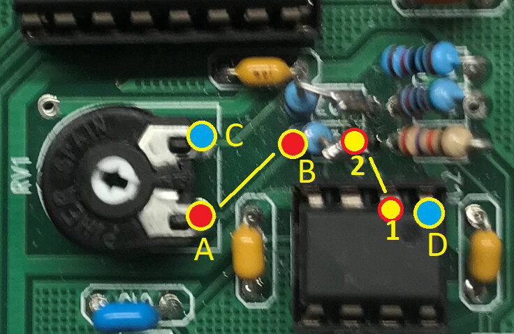
Please check the connection 1 to 2 marked in these pictures:
Hello,
I give up. I am very disappointed with the kit. However, let me first say that I have no complaint with the support, you have been very patient and pedagogical. But the kit was obviously faulty from the beginning; missing resistors and several resistors with the wrong value. I do’t know what to do, I am sitting with an unusable product.